Automotive Window Frame Manufacturing Solution | 2D Wire Bending & Welding Machine
Automotive Window Frame Manufacturing Solution
Integrated 2D Wire Bending and Welding for Pickup Truck, Commercial Vehicle, Side Window, Rear Window, and Custom Automotive Wire Frame Production
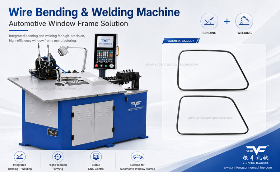
Overview
An automotive window frame manufacturing solution combines wire-forming technology, positioning control, and welding into a coordinated production process for vehicle window support structures and related automotive wire frames.
For many pickup truck, commercial vehicle, utility vehicle, side window, rear window, and door-frame applications, the component geometry is primarily planar or near-planar. This makes CNC 2D wire bending particularly suitable for creating straight sections, corners, radii, mounting features, and closed or semi-closed frame profiles.
When welding is integrated into the same production system, the formed wire frame can be positioned, clamped, joined, and discharged without unnecessary transfer between separate bending and welding stations.
The manufacturing relationship is straightforward:
Automotive Window Frame → CNC Wire Feeding and Straightening → 2D Wire Bending → Positioning and Clamping → Welding → Dimensional Inspection
Yinfeng develops this type of manufacturing solution around the customer's actual frame drawing, wire material, welding requirement, production volume, and tolerance target.
This is an industry manufacturing solution rather than a standard machine specification page. The objective is to explain how automotive window frames can be produced efficiently and consistently using integrated wire bending and welding technology.
What Is an Automotive Window Frame?
A wire-based automotive window frame is a formed metal structure used to support, reinforce, position, or define the geometry around a vehicle window or related body opening.
Depending on the vehicle platform and component design, the frame may include:
Long straight wire sections
Multiple corner bends
Radius transitions
Offset sections
Mounting features
Closed or semi-closed profiles
Welded joining points
Reinforcement sections
Symmetrical or asymmetrical frame geometry
These wire structures can be used in:
Pickup Trucks
Commercial Vehicles
Utility Vehicles
Automotive Doors
Side Window Assemblies
Rear Window Assemblies
Custom Vehicle Body Structures
Special Vehicle Platforms
The exact function varies by vehicle design. Some frames act as structural supports, while others provide reinforcement, locating geometry, mounting support, or part of a larger welded vehicle assembly.
Because the component must fit correctly into the vehicle body or subassembly, dimensional repeatability is a critical manufacturing requirement.
Typical Products Manufactured
An integrated 2D wire bending and welding solution can be developed for products such as:
Pickup Truck Window Frames
Commercial Vehicle Window Frames
Side Window Support Frames
Rear Window Support Frames
Door Window Wire Frames
Automotive Reinforcement Wire Frames
Custom Welded Automotive Wire Structures
Other related products may include formed automotive support components, reinforcement wires, mounting frames, and special planar wire structures.
Actual production feasibility depends on wire diameter, material, frame dimensions, bend geometry, weld-joint design, tolerances, tooling arrangement, and target production speed.
Industry Applications
Pickup Truck Manufacturing
Pickup trucks may use formed wire structures around side windows, rear windows, cabin components, door assemblies, or special body structures.
A CNC wire bending and welding solution is suitable where the frame requires repeatable planar geometry and a welded closure or joining point.
Commercial Vehicle Production
Commercial vehicles often use larger and more varied body structures than passenger cars. Window-support frames may therefore require long straight sections, multiple bends, custom dimensions, and robust welded joints.
Integrated wire bending and welding can help standardize the production process for repeated commercial vehicle frame models.
Automotive Body Component Manufacturing
Tier suppliers and automotive component manufacturers may produce window frames as part of a larger door, cabin, side-wall, or body reinforcement assembly.
For these suppliers, repeatable dimensions and reliable welding position are essential because the wire frame must interface correctly with other metal components.
Automotive Seat and Interior Structures
Although the primary application of this solution is window-frame production, similar 2D forming and welding methods may also be relevant to selected automotive seat, interior-support, and planar reinforcement structures where the geometry and process requirements are comparable.
OEM Automotive Component Production
OEM and Tier 1/Tier 2 production environments typically require stable processes, traceable manufacturing parameters, repeatable tooling, and controlled inspection methods.
The machine and tooling solution should therefore be developed around the approved drawing, material specification, welding requirement, and quality standard.
Custom Vehicle Frame Manufacturing
Special-purpose vehicles, utility vehicles, modified commercial vehicles, and low-volume platforms may require customized window-frame geometries.
CNC programming and dedicated tooling allow different frame designs to be developed without relying entirely on manual forming.
Manufacturing Challenges
Automotive window frames appear simple, but producing them consistently at industrial scale involves several manufacturing challenges.
Dimensional Consistency
The overall width, height, corner positions, and joining location must remain consistent from one frame to the next.
Small dimensional errors can cause fitment problems during vehicle assembly.
Precise Bend Angle Control
Each bend affects the final frame geometry.
If one angle is incorrect, the error can accumulate across the complete frame and change the welding position or overall dimensions.
Frame Symmetry
Symmetrical frame designs require balanced bending accuracy on both sides.
Variations in feed length, bending angle, or tooling position can cause visible or functional asymmetry.
Repeatable Wire Length
The feed system must deliver the correct wire length for each segment of the frame.
Repeatable feeding is essential for maintaining corner position, overall dimensions, and weld-joint alignment.
Welding-Position Accuracy
The two ends of the formed frame must meet at the correct position before welding.
Incorrect alignment can cause poor joint geometry, dimensional distortion, or inconsistent weld penetration.
Welding Deformation
Heat generated during welding can distort the frame.
The process must therefore control clamping, fixture support, heat input, and joint position.
Fixture Positioning
A stable fixture is required to hold the frame in the correct geometry during welding.
Poor fixture design can allow movement, twisting, or dimensional variation.
Material Surface Protection
Automotive components may require clean surfaces for later coating, painting, plating, or assembly.
Tooling and material handling should minimize unnecessary scratches, dents, and surface damage.
Batch Consistency
A qualified process must maintain similar geometry and weld quality throughout the production batch, not only during initial sample production.
Production Efficiency
Automotive manufacturing requires controlled cycle time, reduced manual transfer, repeatable setup, and efficient handling between operations.
Manufacturing Requirements
A reliable automotive window frame production process should control the following factors:
Wire diameter and material consistency
Wire straightness
Feed-length accuracy
Bend angle and bend position
Corner radius
Frame width and height
Diagonal dimensions
Frame flatness
Joint alignment
Welding position
Welding heat input
Fixture repeatability
Surface condition
Final dimensional tolerance
Production cycle time
The process should be developed from the actual product drawing rather than from machine capacity alone.
Why Use an Integrated Wire Bending and Welding Solution?
An integrated system combines several operations that might otherwise be performed on separate machines.
The process can include:
Automatic Wire Feeding
Wire Straightening
CNC Length Control
2D Wire Bending
Frame Positioning
Fixture Clamping
Welding
Finished Frame Output
This approach offers several practical advantages.
Reduced Manual Transfer
In a separate-process system, the operator may need to move the bent frame from the bending machine to a welding station.
Integrated production reduces unnecessary handling between these steps.
Lower Positioning Error
When bending, positioning, and welding are developed as one controlled sequence, the frame can be located more consistently before welding.
Reduced Labor Dependence
Manual frame transfer, manual positioning, and manual welding alignment can increase variation.
Automation reduces dependence on repeated operator handling.
Better Dimensional Repeatability
The frame remains within a defined process from wire feeding through final joining.
This makes it easier to control the relationship between bend positions and weld location.
Shorter Production Flow
Combining forming and welding can reduce work-in-process movement and simplify factory layout.
Easier Program-Based Production
Different frame models can be managed through CNC programs together with the appropriate tooling and fixtures.
Integrated Solution vs. Separate Bending and Manual Welding
A conventional production method may use:
Wire straightening
Cutting
Separate bending
Manual unloading
Manual transfer
Fixture loading
Manual positioning
Welding
Unloading
Inspection
An integrated wire bending and welding solution can reduce several of these transfer and positioning stages.
This does not eliminate the need for proper tooling, welding validation, or inspection. It changes the process from multiple loosely connected operations into a more coordinated production system.
Recommended Materials
Material selection for automotive window frames depends on structural, welding, corrosion, surface, and OEM requirements.
Suitable materials may include: Low-Carbon Steel Wire/Stainless Steel Wire/Galvanized Wire/High-Strength Automotive Wire/ Customer-Specified Steel Wire
Low-Carbon Steel Wire
Low-carbon steel offers good general formability and weldability for many welded wire-frame applications.
Stainless Steel Wire
Stainless steel may be selected where corrosion resistance or specific material performance is required.
Welding method and heat control must be matched to the selected grade.
Galvanized Wire
Galvanized wire provides a zinc-coated surface for corrosion protection.
The welding process must consider the coating, joint quality, fumes, and any required post-weld surface treatment.
High-Strength Automotive Wire
Higher-strength materials may be used where additional structural performance is required.
These materials can increase bending force, springback, tooling load, and welding-process requirements.
Customer-Specified Steel Wire
Automotive customers may specify a particular wire grade, supplier, coating, strength level, or OEM material standard.
The production process should be developed around that specification.
Final material selection depends on:
Required strength
Formability
Weldability
Corrosion resistance
Surface treatment
Operating environment
OEM specification
Final assembly requirements
Production Process
A complete automotive window frame manufacturing process can include the following stages.
1. Drawing Analysis
The process begins with a detailed review of the 2D or 3D product drawing.
Important information includes:
Overall frame dimensions
Wire diameter
Material
Bend angles
Bend radii
Straight-section lengths
Welding position
Joint design
Dimensional tolerances
Surface requirements
The drawing determines the machine configuration, tooling strategy, welding method, and inspection plan.
2. Material Preparation
The correct wire material is prepared according to the approved specification.
Material consistency is important because changes in tensile strength, diameter, or surface condition can affect bending and welding behavior.
3. Wire Straightening
Wire from a coil naturally contains residual curvature.
The straightening system reduces this curvature before forming.
Good straightening helps improve:
Frame flatness
Straight-section accuracy
Bend consistency
Final weld alignment
4. CNC Wire Feeding
The machine feeds the programmed wire length into the bending area.
Accurate feeding establishes the position of each bend and directly affects the final frame dimensions.
5. 2D Wire Bending
The CNC bending system forms the wire according to the programmed frame geometry.
Typical operations may include:
Right-angle bends
Acute bends
Obtuse bends
Radius corners
Long straight sections
Repeated symmetrical features
Semi-closed frame geometry
Closed frame geometry before welding
6. Frame Positioning
After the main forming sequence, the frame is positioned so that the joining ends align correctly.
This stage is essential for accurate welding.
7. Welding Fixture Clamping
A dedicated fixture holds the formed frame in the required geometry.
The fixture should support critical areas while allowing access to the welding joint.
8. Automatic Welding
The joining point is welded according to the selected welding process and joint requirement.
The welding system should maintain a stable relationship between:
Joint position
Clamping force
Heat input
Weld duration
Frame geometry
9. Dimensional Inspection
The welded frame is checked against the required dimensions.
Inspection may include manual gauges, dedicated fixtures, measuring tools, or automated inspection systems depending on the production requirement.
10. Surface Treatment if Required
Depending on the component specification, the frame may require:
Cleaning
Grinding
Coating
Painting
Plating
Corrosion protection
Other surface treatment
11. Final Inspection
The finished frame is checked before packaging or transfer to the next assembly stage.
Welding Integration
Welding integration is one of the most important parts of an automotive window frame manufacturing solution.
The welding station must not be treated as an isolated function. Its design should be coordinated with the bending process, frame geometry, fixture position, material, and final tolerance requirement.
Benefits of Integrated Welding
Integrated welding helps reduce:
Manual Frame Transfer
Repositioning Error
Labor Dependence
Dimensional Variation
Work-in-Process Handling
Separate Fixture Loading
Stable Welding Position
The welding point should remain consistent relative to the frame geometry.
A stable joint position makes it easier to maintain repeatable weld quality and frame dimensions.
Fixture Design
The fixture must support the frame during welding while preventing unwanted movement.
Fixture design should consider:
Reference points
Clamping locations
Part access
Weld access
Thermal expansion
Unloading
Repeatability
Heat-Input Control
Excessive or inconsistent heat can cause:
Local distortion
Frame warping
Surface damage
Joint inconsistency
The welding process should therefore use controlled and repeatable parameters suitable for the selected material and joint.
Frame Deformation Control
Frame deformation can be reduced through a combination of:
Correct fixture support
Stable clamping
Controlled weld energy
Proper joint design
Consistent material
Optimized welding sequence
Post-weld dimensional inspection
Quality Control
Automotive window frame quality should be controlled throughout the manufacturing process.
Overall Dimensions
Check the finished frame width, height, and other critical external dimensions.
Diagonal Dimensions
For rectangular or near-rectangular frames, diagonal measurement is an effective way to check squareness and overall geometry.
Bend Angle
Each bend should remain within the specified angular tolerance.
Frame Flatness
The finished frame should remain within the required flatness specification.
Welding Strength
The welded joint should meet the required mechanical-performance standard for the application.
Weld Position
The joint should remain in the specified location and alignment.
Symmetry
Symmetrical products should be checked for left-right dimensional consistency.
Surface Quality
Inspect for:
Scratches
Dents
Coating damage
Excess weld material
Heat discoloration where relevant
Surface contamination
Repeatability
Parts produced at different times in the same batch should remain within the approved dimensional and welding limits.
Fixture Consistency
Inspection and welding fixtures should be checked periodically to ensure wear or movement has not changed the reference geometry.
Recommended Yinfeng Equipment
For this application, Yinfeng recommends the:
2D Wire Bending and Welding Machine for Automotive Window Frame Production
This equipment is designed around the manufacturing requirements of planar automotive wire frames and can integrate:
Wire Feeding
Wire Straightening
2D Wire Bending
Frame Positioning
Fixture Clamping
Welding
The system is suitable for automotive window-frame projects where the component requires CNC bending followed by a controlled welded joint.
The equipment should be configured around the actual product rather than selected from a generic specification alone.
Final machine configuration should be confirmed according to wire diameter, material, frame dimensions, bend geometry, welding position, production speed, and customer drawing.
When Is a Standard CNC Wire Bending Machine Sufficient?
A standard CNC wire bending machine may be suitable when:
The part does not require welding
Welding is performed in an existing separate process
The frame is open rather than closed
Production volume does not justify integrated welding
The customer already has a dedicated welding line
In these cases, a standalone 2D wire bending machine may be a more appropriate solution.
When Is a 3D Wire Bending Machine Relevant?
A 3D wire bending machine may be considered when the automotive component includes significant out-of-plane geometry.
Examples include:
Multi-plane support frames
Offset mounting sections
Spatial wire structures
Complex non-planar brackets
For primarily planar automotive window frames, 2D bending is generally the more direct manufacturing approach.
Customer Value
The objective of an integrated automotive window frame manufacturing solution is not simply to automate bending.
The value comes from controlling the complete relationship between material feeding, bending geometry, frame positioning, welding, and final inspection.
Potential customer benefits include:
More consistent frame geometry
Reduced manual transfer
Lower positioning variation
More controlled welding location
Improved batch repeatability
Reduced dependence on manual bending
Simplified production flow
Faster repeat production
Easier management of different frame models
Better integration between forming and welding operations
The actual production benefit depends on product design, volume, material, factory layout, and existing manufacturing process.
Why Choose Yinfeng?
Yinfeng develops CNC wire bending and forming solutions based on actual customer components and production requirements.
For automotive window frame projects, Yinfeng can support the complete process from technical evaluation through machine implementation.
CNC Wire Bending Experience
Yinfeng develops CNC wire bending equipment for different 2D and 3D wire-forming applications.
This experience is relevant to automotive components requiring precise feed lengths, repeatable bending, and customized forming sequences.
Customized Tooling
Window frames require tooling developed around the actual product geometry.
Yinfeng can design:
Bending Tools
Wire Guides
Positioning Fixtures
Welding Fixtures
Clamping Devices
Inspection Fixtures
Welding Integration
Yinfeng can develop the welding function as part of the overall forming solution rather than treating welding as an unrelated secondary operation.
Drawing and Sample Evaluation
Customers can provide drawings, photographs, videos, or physical samples for technical review.
Production-Process Development
The manufacturing process can be evaluated step by step, including:
Material feeding
Straightening
Bending sequence
Frame positioning
Welding
Inspection
Operator Training
Yinfeng can provide training covering machine operation, CNC programming, product changeover, basic maintenance, and production-process adjustment.
Technical Support
Technical support is available for machine operation, programming, tooling, and production-related questions.
Spare Parts Support
Yinfeng provides spare parts support for the supplied equipment throughout its service requirements.
Customized Solutions
Machine structure, tooling, control functions, and auxiliary equipment can be configured according to the customer's product and manufacturing process.
Information Required for Technical Evaluation
To evaluate an automotive window frame manufacturing project, customers should provide as much of the following information as possible:
2D Product Drawing
3D Product Drawing
Wire Diameter
Wire Material
Frame Dimensions
Bending Angles
Bend Radii
Welding Positions
Welding Type
Required Production Speed
Annual Production Quantity
Dimensional Tolerance
Surface Requirements
Sample Photos
Physical Sample if Available
Additional useful information includes:
Material tensile strength
Existing production method
Current cycle time
Quality problems with the current process
Required automation level
Upstream and downstream equipment requirements
This information allows the machine, tooling, welding process, and production sequence to be evaluated as one manufacturing system.
Frequently Asked Questions
What machine is used to make pickup truck window frames?
A pickup truck window frame with primarily planar geometry can be produced using a CNC 2D wire bending machine. If the finished frame requires a welded joint, an integrated 2D wire bending and welding machine can combine feeding, straightening, bending, positioning, clamping, and welding in one production solution.
Can one machine complete both bending and welding?
Yes. An integrated wire bending and welding system can be designed to complete CNC bending and the subsequent welding operation within one production cell. Final configuration depends on the frame geometry, material, welding method, and production requirements.
What wire materials can be processed?
Typical materials may include low-carbon steel wire, stainless steel wire, galvanized wire, high-strength automotive wire, and customer-specified steel wire. Final material suitability depends on formability, weldability, strength, corrosion resistance, surface requirements, and OEM specifications.
Can different window-frame designs be produced on one machine?
Different frame designs may be produced by changing CNC programs and, when required, dedicated tooling or fixtures. Compatibility depends on wire diameter, frame size, bending geometry, welding position, and machine working range.
How is welding deformation controlled?
Welding deformation is controlled through stable fixture design, correct clamping, controlled heat input, consistent joint positioning, appropriate welding parameters, and dimensional inspection after welding.
Can the machine produce commercial vehicle window frames?
Yes. Commercial vehicle window frames are suitable applications when their geometry, dimensions, material, and welding requirements are compatible with the selected machine and tooling configuration.
Is custom tooling available?
Yes. Yinfeng can develop customized bending tools, wire guides, positioning fixtures, welding fixtures, clamps, and inspection fixtures according to the customer's frame drawing.
Can programs be saved and reused?
Yes. CNC production programs can be stored and recalled for repeat production, helping reduce setup time when the same frame model is manufactured again.
Can Yinfeng test customer samples?
Yes. Customers can provide drawings, sample photographs, production videos, wire specifications, or physical samples for technical evaluation and process development.
Is operator training available?
Yes. Yinfeng can provide operator training covering machine operation, CNC programming, product changeover, tooling adjustment, routine maintenance, and basic troubleshooting.
Related Equipment
2D Wire Bending and Welding Machine for Automotive Window Frame Production
Recommended for primarily planar automotive window frames requiring integrated bending and welded closure or joining.
CNC Wire Bending Machine
Suitable for 2D wire components that do not require integrated welding or where welding is performed separately.
3D Wire Bending Machine
Suitable for automotive wire components requiring significant out-of-plane bends, spatial geometry, or multi-directional forming.
Related Industry Solutions
Automotive Seat Frame Manufacturing Solution
Automotive Headrest Frame Manufacturing Solution
Automotive Wire Bracket Manufacturing Solution
Commercial Vehicle Wire Frame Manufacturing Solution
Custom Welded Wire Frame Manufacturing Solution
Send Your Automotive Window Frame Drawing for Technical Evaluation
Automotive window frame production should be developed around the actual component, not around a generic machine specification.
To evaluate your project, send Yinfeng:
Product Drawing
Wire Diameter
Wire Material
Welding Requirement
Target Production Speed
If available, also provide the required tolerances, sample photos, annual quantity, and current production method.
Yinfeng can review the complete manufacturing process—including wire preparation, CNC bending, positioning, welding, tooling, inspection, and production flow—and recommend a suitable automotive window frame manufacturing solution.
The goal is to develop a stable production process for the customer's specific automotive component, rather than simply supply a standalone machine.